V2 · 12 servosDated experiment
Three Short-Rod Leg Mechanisms: What the CAD Tests Found
A direct pushrod, a supported relay yoke, and an offset cascade compared by rod length, modeled range, pose coverage, and interference.
Published Updated 4 min read
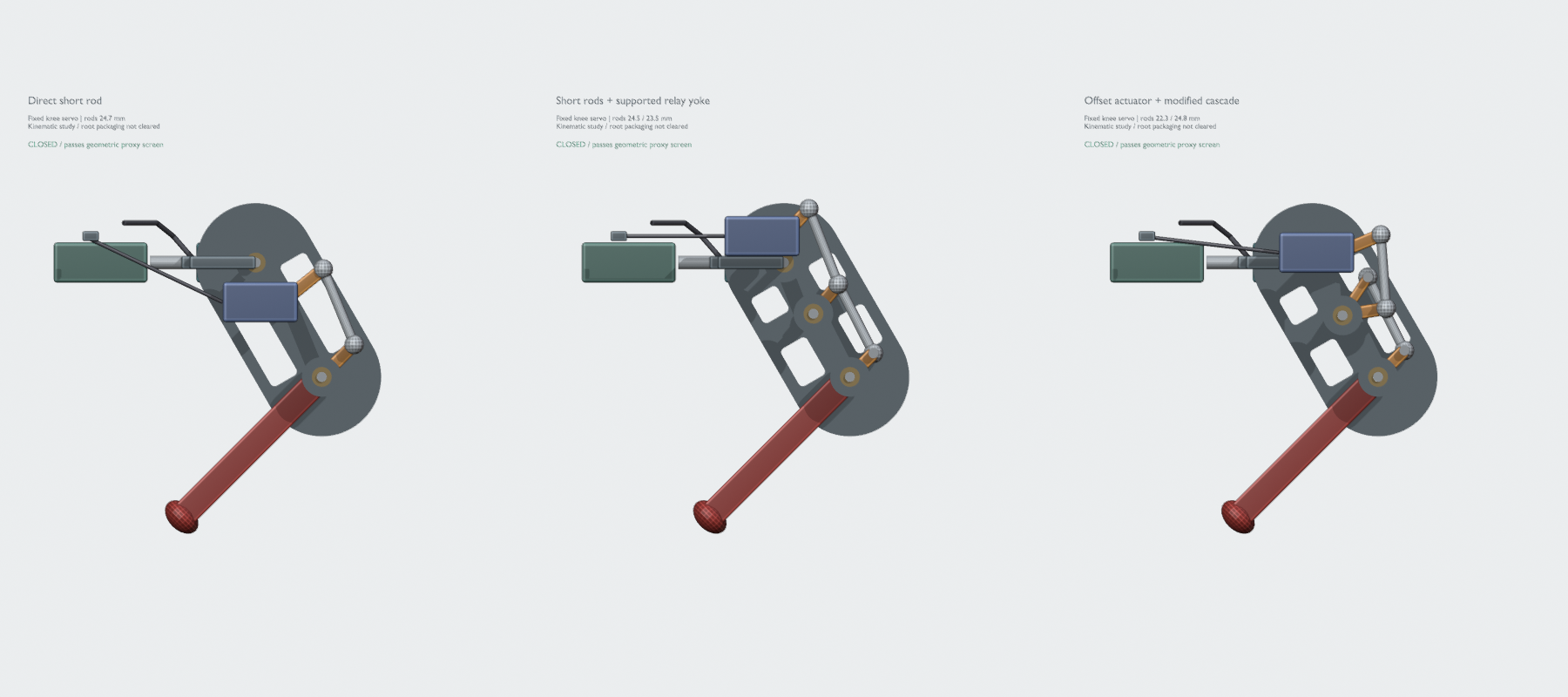
Keeping the knee motor on the body
This September 9 study investigated driving a knee through short rigid rods while its servo stays fixed to the chassis, even when the leg rolls sideways. Keeping that motor and cable off the moving leg was a design constraint. The study compared three mechanisms against the same requested poses and useful knee-travel target of 160–180°.
None met the complete brief. The supported relay yoke, Variant 2, is the next research candidate. It is not a released printable leg and is separate from the four-leg CAD assembly.
The constraints used in the study
The available M3×30 bolt was provisionally interpreted as allowing at most 25 mm between rod-end pivot centers. That is an assumption about the design envelope, not a measurement of a bolt assembled with its nuts and end fittings. The rod lengths below are center distances, not a finished hardware cut list.
All three mechanisms use 40 mm effective upper links and 60 mm lower links. The knee and roll servos stay chassis-fixed; the proximal hip-pitch servo moves with the roll carrier. Each modeled servo case occupies a 22.8 × 12.2 × 28.5 mm envelope. The assumed input interval is a fixed 180° span, indexed from 10° to 190° in the geometric model. Those angles are not calibrated PWM commands.
The baseline came from the OpenHarmony Puppy V2 leg reference. Its 27 imported meshes were preserved for comparison. Credit and the original reference are in the V2 build guide.
Comparing the three mechanisms
| Mechanism | Rod center distances | Useful modeled knee travel at hip 0°, roll 0° | Modeled travel with mesh checks at hip 30°, roll 0° | Pose probes passing |
|---|---|---|---|---|
| 1 · Direct short rod | 24.7 mm | 96.5° (53.7–150.2°) | 133.1° (34.9–168.0°) | 7 / 15 |
| 2 · Supported relay yoke | 24.5 + 23.5 mm | 132.1° (23.0–155.2°) | 133.3° (30.6–163.9°) | 9 / 15 |
| 3 · Offset actuator and cascade | 22.3 + 24.8 mm | 121.3° (27.9–149.2°) | 125.0° (27.9–152.9°) | 9 / 15 |
The range columns are different tests at different hip angles. The first uses geometric transmission, rod-end clearance, and folding checks. The second also checks the modeled surface envelopes, in 1° input steps. They must not be combined into one set of safe joint limits for the robot.
The direct rod uses the fewest rods and pivots, but loses usable motion as hip angle changes. Its 16 mm input crank is large for the modeled servo, and deep folding and rear tuck are particularly limited.
Variant 2 divides the transmission at a supported rocker on the upper leg. Its two rods share a relay pin, with their centers 7 mm apart across the leg; a symmetric yoke receives the drive at the knee. It reaches more requested poses than the direct rod, but adds a pivot and articulated rod ends. The folded shin and sideways clearance around the fixed actuator remain limits.
Variant 3 separates the relay’s input and output arms and offsets the actuator. That permits phase adjustment, but introduces a second relay pin and a more nonlinear relationship between servo and knee movement. Its rearward poses lose range, and the added hardware brings more potential friction and play.
What stopped Variant 2 from passing
At neutral hip angle its useful geometric range is about 132°, short of the 160–180° target. Moving the servo horn’s starting orientation can shift where that travel occurs, but cannot enlarge the assumed 180° actuator span.
| Requested probe | Result in the modeled study |
|---|---|
| Neutral stand, low crouch, full sit, front wave | Passed the checked geometric and surface envelopes |
| Almost-straight forward extension | Outside the fixed servo window on the retained linkage branch |
| Near-floor fold | Shin, rod, or shaft interference |
| Rear tuck | Rod/crank clearance and interference with the roll-servo envelope |
| Wide and narrow stance | Fixed knee-servo, cheek, or rod-end interference |
These are single-leg pose probes. A probe named “sit” or “wave” does not prove that four legs can balance the robot or move through the transition.
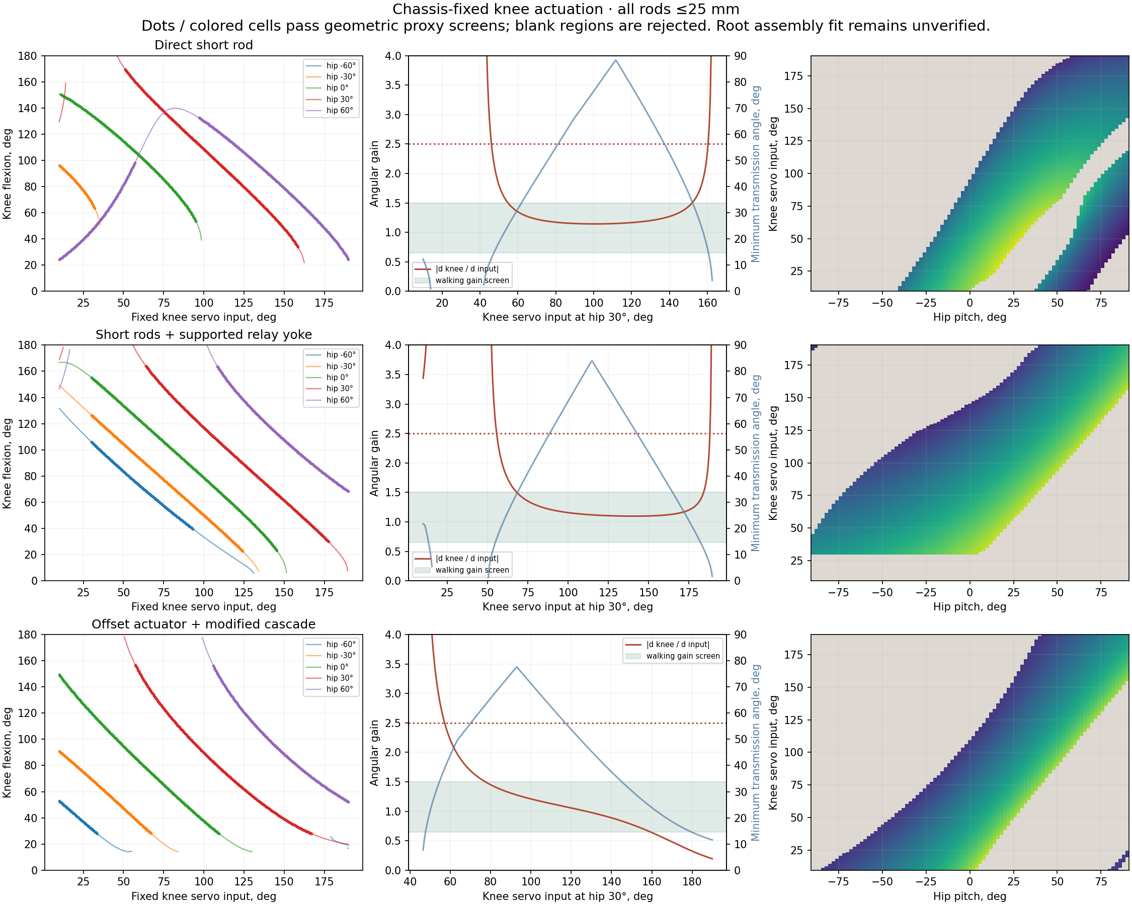
Plots from the study’s saved analysis. Rejected samples are retained.
The 14 mm internal channel is too narrow for every desired roll position of the fixed input and its rod ends. Opening the root of that channel and moving the roll-servo package are recorded next investigations, not completed repairs.
What these numbers establish
The study retained the same linkage assembly branch during its motion search. It screened near-aligned transmission angles, excessive or weak angular gain, rod-end clearance, folding, and selected mesh intersections. Its 20° minimum transmission angle and absolute gain range of 0.4–2.5 are declared research criteria, not general mechanical standards.
The saved verification checked rod closure and preserved baseline geometry. The modeled cheeks, shaft and bush envelopes, and simplified servo cases do not establish fastener engagement, print fit, strength, backlash, cable bend clearance, or loaded operation. No result here establishes production-ready parts or whole-robot stability.
This article transcribes the LEG_R&D study README, the three variant parameter
and pose tables, and the saved analysis figures reviewed on September 10.
It reports the existing study; the motion search and physical tests were not
rerun for this article.
Three Short-Rod Leg Mechanisms: What the CAD Tests Found
https://ainek.io/posts/2026-09-09-leg-mechanism-study/