V2 · 12 servosDated experiment
Narrowing the Chassis and Making Room for the Face
The 103-to-51.2 mm chassis revision, board-clearance measurements, and a camera-cable recess moved beneath the face.
Published 4 min read
A narrower body around the leg mechanism
Much of the recent work has gone into modeling the chassis and changing how the legs fit around it. The September 10 assembly explored a wide body with three electronics boards. On September 17, the chassis was narrowed from 103 mm to 51.2 mm, using the nominal PCB width of the selected 1.9-inch display as the reference. These dimensions describe the chassis envelope; the legs and outer shell extend beyond it.
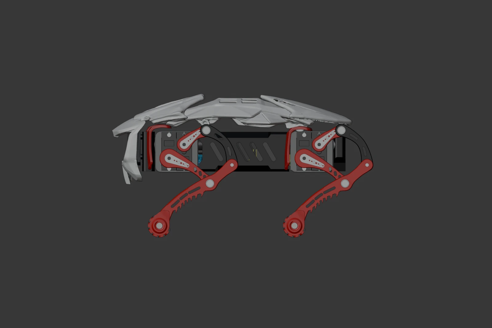
September 20 assembly view. The measurements below belong to the dated chassis and cable-routing revisions, before some of the later shell changes.
Moving the sides while preserving the interfaces
Each side assembly moved inward 25.9 mm. The leg meshes, bearing bores, servo geometry and link lengths stayed unchanged in this width revision. The top plate, bottom plate, front carrier and rear cover were rebuilt around their translated interfaces. Later leg changes have their own compact-leg record.
| Feature | Earlier layout | September 17 revision |
|---|---|---|
| Chassis outer width | 103 mm | 51.2 mm |
| Side assemblies | Wide-body positions | Each moved inward 25.9 mm |
| Rear cover | Earlier wide cover | 47.2 mm wide, maintaining a 2 mm inset on each side |
| Plate thickness | 3 mm nominal | Retained; existing top support-contact regions remain 3.2 mm |
| Q6A board and tray | Part of the wide packaging study | Retired from this narrow layout and retained as a hidden design variant |
| P4 and PCA9685 models | Existing board geometry and positions | Retained for further mounting and clearance work |
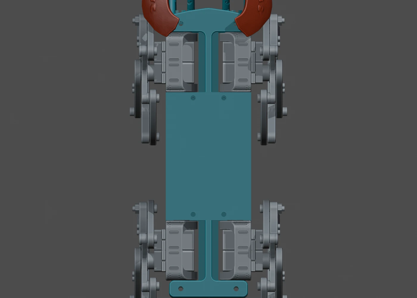
September 17 CAD detail. The narrowed center spans connect the original side interfaces. The view is cropped at the ends; it is not a complete robot outline.
The old center-strip electronics posts and partial mounting holes were removed or closed. Retiring the Q6A’s wide-body fit is a mechanical decision in this revision, not a record of deploying or removing an onboard operating system. The narrower body still needs a coherent board-mounting and cable layout.
Measuring board clearance during shoulder rotation
The follow-up audit tested the four Part_003 housings against the P4 and PCA9685 models in the narrow chassis. It found the following conservative clearance bounds over the tested rotations:
| Housing pair | Board model | Tested rotation relative to neutral | Conservative clearance |
|---|---|---|---|
| Rear left / right | ESP32-P4 | About 19° inward to 125° outward | At least 1.970 / 1.967 mm |
| Front left / right | PCA9685 | 13.01° inward to 140° outward | At least 0.788 mm on each side |
The bounds use the box enclosing each board and its modeled components. The separate fixed-chassis check sampled 308 shoulder poses, with no intersection above its 0.01 mm³ threshold. Further inward rotation did reach the boards: approximately 33° at the rear and 22.3° at the front in that model. Those contact estimates are geometric findings, not calibrated servo stops.
The submillimeter clearance near the PCA9685 matters when routing wires and allowing for connectors and print tolerances. This audit covered housings, boards and fixed chassis parts. It did not establish clearance for the moving links, flexible cables or the evolving shell as a complete assembly.
Moving the camera cable below the face
On September 18, the front panel’s old top-center cable recess was closed and a new recess cut into its bottom edge. Simply mirroring the old opening still intersected the wider cable tail in the preview, so the inner profile changed.
| Cable opening | Earlier profile | Revised bottom-edge profile |
|---|---|---|
| Position | Top center | Bottom center |
| Mouth width | 22.35768 mm | Retained |
| Inner flat | Earlier narrower profile | 17 mm |
| Depth | 4 mm | 4.8 mm |
| Two central ventilation slots | 21 mm high | 18.2 mm high, leaving a 2 mm bridge above the recess |
| Outer ventilation slots | 21 mm high | Retained |
The front face, 3 mm central wall, mounting holes and bearing interfaces were preserved. The saved-panel check found one connected solid and no overlap with the modeled cable preview, bottom cover or LCD carrier. Actual cable bending and routing still need a physical check.
What this revision establishes
The chassis work provides a narrower saved assembly, measured board-clearance evidence and a cable opening fitted to the current preview. It does not yet establish a fully mounted, wired or load-tested robot. The next checks belong to the chosen combination of chassis, compact legs and shell, since those parts have continued to change.
Read the companion updates on compact legs and horn fit and shell development. The September 10 body post preserves the earlier wide layout and its electronics options.
Design records
These are the original dated records, with local workspace prefixes shortened. Their reported geometry checks were reviewed for this article, not rerun.
Narrowing the Chassis and Making Room for the Face
https://ainek.io/posts/2026-09-21-chassis-packaging/