V2 · 12 servosDated experiment
Compact Legs: Geometry, Print Faces and Horn Fit
Comparing the 24/41/60 and 22/36/55 mm legs, retaining tested articulation, and correcting a horn cavity after a failed printed fit.
Published 5 min read
Making the leg more compact
The new leg has continued to change since the first printed prototypes. Recent work includes a direct connecting rod, level servo shafts, flat printing faces, shorter links and a horn pocket revised after a real assembly problem. The dimensions below identify the individual iterations; they should not be combined into an assumed final parts list.
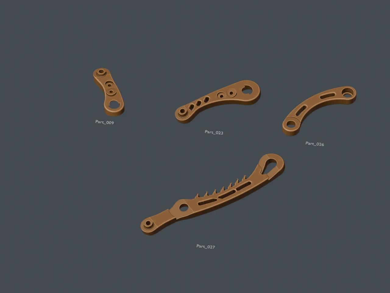
September 18 flat-face iteration. This layout explains the part roles and printing orientation; the shorter compact exports came afterward.
A shorter path from the crank to the lower leg
The earlier mechanism used a coupler and relay rocker between the input crank and lower assembly. The later arrangement connects Part_009 to Part_027 through Part_026. Part_023 remains the upper carrier driven by the other planar servo, and the shoulder supplies the third actuator on each leg.
The September 18 level-shaft revision retained a 24 mm crank, 24 mm pickup, 41 mm rod, 40 mm carrier and 60 mm lower leg. Both servo shafts were placed at the same height, 12.5 mm apart horizontally. Short screw envelopes replaced three long joint fasteners and their separate nut pockets. The modeled M3 × 6 mm screws had 2.7 mm nominal support engagement after the bearing and washer stack. The plain 3 mm holes alone do not establish screw grip in a print.
That revision also used two separate 12.4 × 4.2 × 5.25 mm rectangular servo shims, one beneath each mounting ear, with 2.2 mm mounting holes. These details belong to the level-shaft iteration; the later upright exports below are a separate saved set.
Comparing the earlier and compact geometry
The September 19 comparison measured an earlier 24/41/60 mm leg against a compact front-left test with 22/36/55 mm dimensions. These three numbers mean crank spacing, rod spacing and knee-to-foot-bolt projected spacing. The upper carrier stayed at 40 mm and the lower-leg pickup at 24 mm.
| Dimension | Earlier leg | Compact front-left test |
|---|---|---|
| Part_009 crank, joint centers | 24 mm | 22 mm |
| Part_026 connecting rod, joint centers | 41 mm | 36 mm |
| Part_023 upper carrier | 40 mm | 40 mm |
| Part_027 linkage pickup | 24 mm | 24 mm |
| Part_027 knee-to-foot-bolt projection | 60 mm | 55 mm |
The compact test’s immediate predecessor had a 38 mm rod: its local edit was 24/38 → 22/36. The table compares against the earlier 24/41/60 baseline, so the two records answer different revision questions.
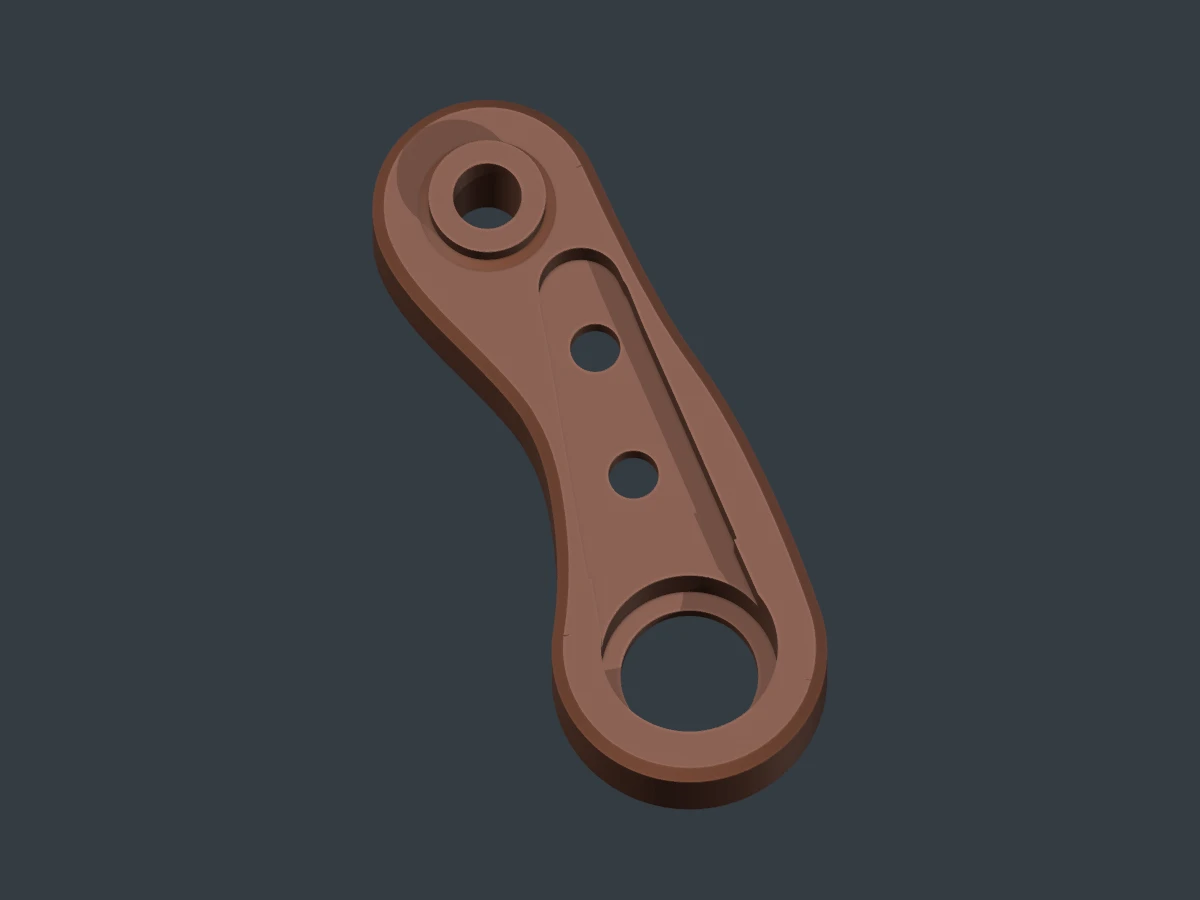
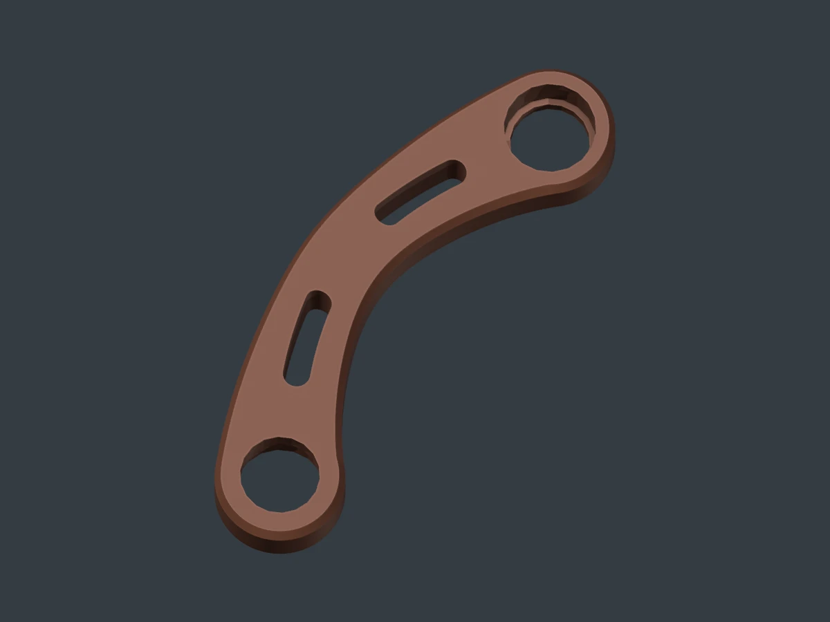
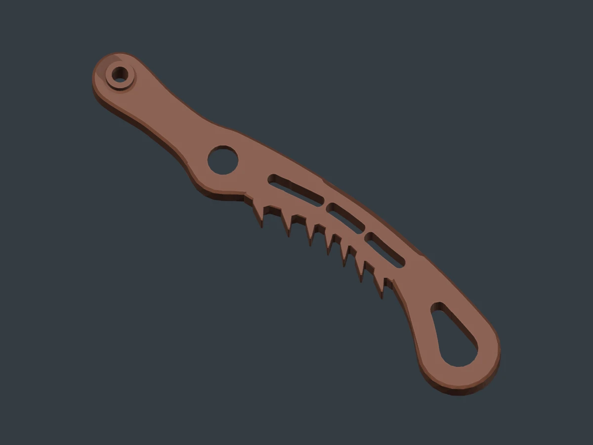
New renders of the recorded upright STL files, with dimensions from the design records. Each part is framed separately; their image sizes are not a common scale.
What happened to the movement?
Nine reference poses were matched by preserving upper- and lower-link orientations and solving a new crank angle. The comparison sampled 520 actuator pairs along the resulting exercise.
| Matched exercise | Earlier leg | Compact test |
|---|---|---|
| Upper-link angular sweep | 90.00° | 90.00° |
| Lower-link orientation change | 54.00° | 54.00° |
| Required crank-input sweep | 98.12° | 100.81° |
| Foot-bolt horizontal extent | 67.268 mm | 66.248 mm |
| Foot-bolt vertical extent | 45.383 mm | 41.200 mm |
The compact design retained the tested angular articulation while the shorter lower leg reduced foot excursion. Horizontal extent decreased about 1.5% and vertical extent about 9.2%. The extra crank rotation is an input requirement, not additional foot articulation.
This is a matched articulation exercise. Foot-bolt extent is neither a walking stride nor sole clearance. The shoulder was held at zero, and these geometric angles are not calibrated servo commands. Full mechanical travel, whole-body collisions and loaded performance were not established here.
When the horn seat fits but the arm will not enter
The printed Part_023 exposed a specific problem: its cylindrical horn seat fitted, but the horn’s arm could not enter the cavity. Comparing the horn reference outlines found agreement within 0.00004 mm after alignment. The horn itself had not been scaled down; the cavity profile had changed through the preceding redesigns.
The correction enlarged only the arm cavity by 5% in its plane, including its length. The enlargement blends near the hub and excludes the cylindrical mating region within a 4.05 mm radius. The floor, exterior carrier shape, pivot axes and mounting holes were retained.
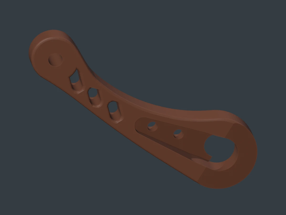
Rendered from the September 19 horn-clearance STL. This is the earlier correction file, separate from the later upright export. A new printed fit is still needed to establish whether the correction works with the purchased horn.
Angled and upright variants
The compact test initially covered one leg: physical front-left, labeled RL in that CAD revision. The later checkpoint inventory retains an angled compact reference and records restoring upright compact legs, both using 22/36/55 mm lengths. Reopening the September 20 saved assembly for this update also found 22 mm crank and 36 mm rod properties on all four main legs, with 55 mm lower-leg properties. That inspection did not rerun motion qualification.
The gait journal records the single-leg walking probes and the work needed to carry those results into a complete current assembly. Older motion clips require retargeting to the chosen mechanism.
Recorded print files
These millimeter STL exports document the upright compact revision. They are experimental parts, with printed fit and loaded strength still to check. They are not a complete robot kit or a claim that the associated fastener, bearing and servo stack has been physically qualified.
| Part | Role / recorded dimension | Download |
|---|---|---|
| Part_009 | 22 mm input crank | Upright STL |
| Part_026 | 36 mm connecting rod | Upright STL |
| Part_027 | 55 mm lower-leg projection | Upright STL |
| Part_023 | Upper carrier, horn-clearance variant | Upright STL |
| Part_020 | One foot shell | Upright STL |
| Part_022 | Mating foot shell | Upright STL |
The earlier 5% horn-arm correction STL is provided separately to document that fit experiment. Keep its revision separate when comparing prints.
Records behind the update
- Level-shaft geometry and fastening notes
- Compact test geometry and saved checks
- Matched-range comparison: method and limits
- Comparison measurements, JSON
- Printed horn-fit problem and correction
- Source and download checksums
The original design checks above were reviewed, not repeated for this post. The new images render the exported geometry. Print materials, settings and unrecorded physical results have not been inferred from those files.
Compact Legs: Geometry, Print Faces and Horn Fit
https://ainek.io/posts/2026-09-21-compact-leg-design/