V2 · 12 servosDated experiment
650 g, revised power packaging and a training stand
The current Blender assembly, battery and charger dimensions, printable support stand, and supported Stand/Walk firmware trials.
Published 3 min read
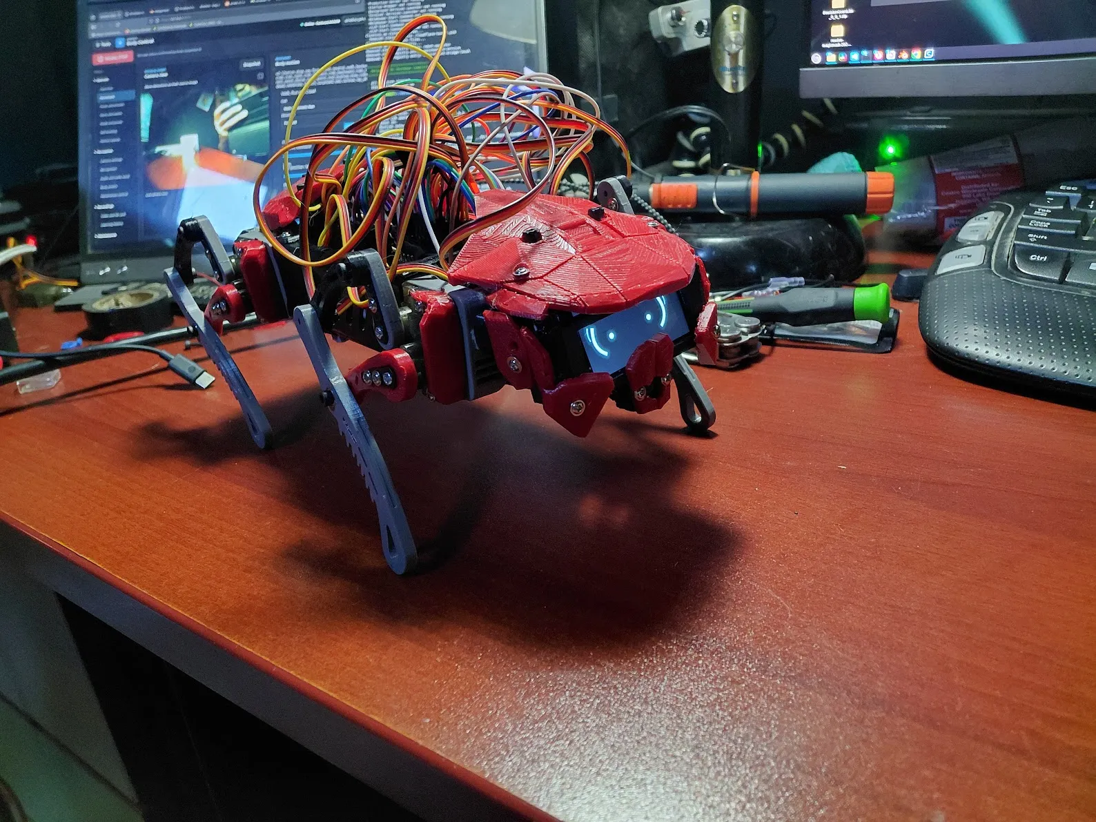
October 21 workbench photograph.
The October 26 hardware record puts the assembled robot at 650 g and confirms that the physical build matches the current Blender design. The earlier 566 g figure belongs to the October 13 assembly. SHARGE is no longer used; the current power assembly has a 2S battery, Mini560 buck converter and HiLetgo 2S USB-C charger.
Parts and packaging
| Part or dimension | Current record |
|---|---|
| Battery pack envelope | 73.6 × 46 × 22 mm |
| Mini560 converter | 30 × 18 × 5.6 mm |
| HiLetgo charger | 36.5 × 17.75 × 1.5 mm bare PCB; 6.8 mm modeled overall height |
| Speaker | 20 × 30 × 6.66 mm |
| Carrier / crank / pickup / rod / lower leg | 35 / 20 / 28 / 38 / 55 mm |
| Front-to-rear shoulder spacing | 173.434 mm |
| Left-to-right shoulder spacing | 63.500 mm |
| Joint feedback | Twelve modified Miuzei MG90S servos through a CD74HC4067 multiplexer |
The current Blender file is Ainekio-Motion-Working.blend, scene Wireless,
with one Blender unit representing one millimetre. The October 26 frame-168
measurement spans 245.85 × 182.79 × 109.06 mm. That is the outline of that
raised-leg pose, not the normal standing footprint.
The power record includes an 8.4 V battery and 5 A buck rating from October 15, a separate 5 V servo rail, common ground and 3.3 V logic. Current pack capacity, loaded current and running time have not been measured. The older power-bank energy and runtime estimates do not describe this pack. The Q6A remains offboard and has its own power.
A new one-piece rear power-carrier STL joins the earlier open-frame and separate retainer exports. The new file is included below; its filename alone does not establish which carrier revision is fitted.
Compact support for motion training
The new fixed training stand uses three printed parts: base, ribbed upright and vent-locating cradle. It replaces the earlier tall tilting/clamping design. The robot rests on the cradle and lifts straight off.
| Stand detail | Dimension or hardware |
|---|---|
| Base footprint | 140 × 110 mm |
| Overall height | 77.1 mm |
| Tray support height | 75.9 mm above the base bottom |
| Locating blades | Two, each 4.0 × 40.0 mm; 42 mm between centers |
| Matching modeled vent slots | 4.4 × 40.4 mm; nominal 0.2 mm clearance per side |
| Blade engagement | 1.2 mm, with tapered lead-in |
| Base-to-upright fasteners | Two M3×20 socket bolts and two M3 nuts |
| Cradle-to-upright fasteners | Two M3×10 socket bolts and two M3 nuts |
| Solid model volume | 58.0 cm³, down from 440.8 cm³; approximately 87% less |
The cradle shoulders carry the tray; the locating blades do not extend into the battery. Base and cradle print flat underneath, and the upright prints on its broad side. Insert the upper nuts through the upright’s side pockets before attaching the cradle.
The volume comparison is geometry, not a slicer filament estimate. Current-pose clearance and mesh topology were checked in Blender. Printed fit, full motion clearance and physical loading still need testing. The stand supports the body; it does not restrain it against an upward movement.
Download the three stand STLs, assembly notes and one-piece power carrier.
Firmware work at the bench
An installed firmware revision rebooted when starting Stand or Walk. The motion
planner was consuming too much of its 16 KiB task stack. Version 0.8.123 moved
the candidate planner into task-owned storage; the compiler’s start_motion
stack figure fell from 8,496 to 3,760 bytes.
After installation on October 25, the supported robot completed Stand and one finite Walk cycle with its feet clear, without rebooting or disconnecting. Those trials verified the repaired command path. They were not floor walking.
The following revisions address a different problem: claiming arrival before the shaft measurements catch up.
| Revision | Change |
|---|---|
0.8.124 | Stand stays pending until fresh feedback verifies its final targets |
0.8.125 | The moving leg must reach each lift/place landmark before the next segment; saved arrival tolerance confirmed at 100 µs after reboot |
0.8.127 source | Boot/wake and inactivity requests go to Freestyle; generated targets use the same feedback executor |
Loaded servo chatter remains unresolved. The earlier 2 mm lift-and-return settling command was installed, but I reported no visible settling movement and continued chatter. The 100 µs value is a shaft-arrival setting, not measured foot clearance.
The next physical comparisons are the loaded rise, foot placement and floor walking with the matching motion model and firmware. Freestyle training results explain why a completed model fit is not yet a reliable standing controller.
Records
This entry follows the October 26 V2 specifications, the training stand’s
Assembly.txt, current STL exports and the P4 firmware log.
Source revisions and file hashes.
650 g, revised power packaging and a training stand
https://ainek.io/posts/2026-10-26-body-power-and-training-stand/