A familiar chassis, rebuilt around a different system
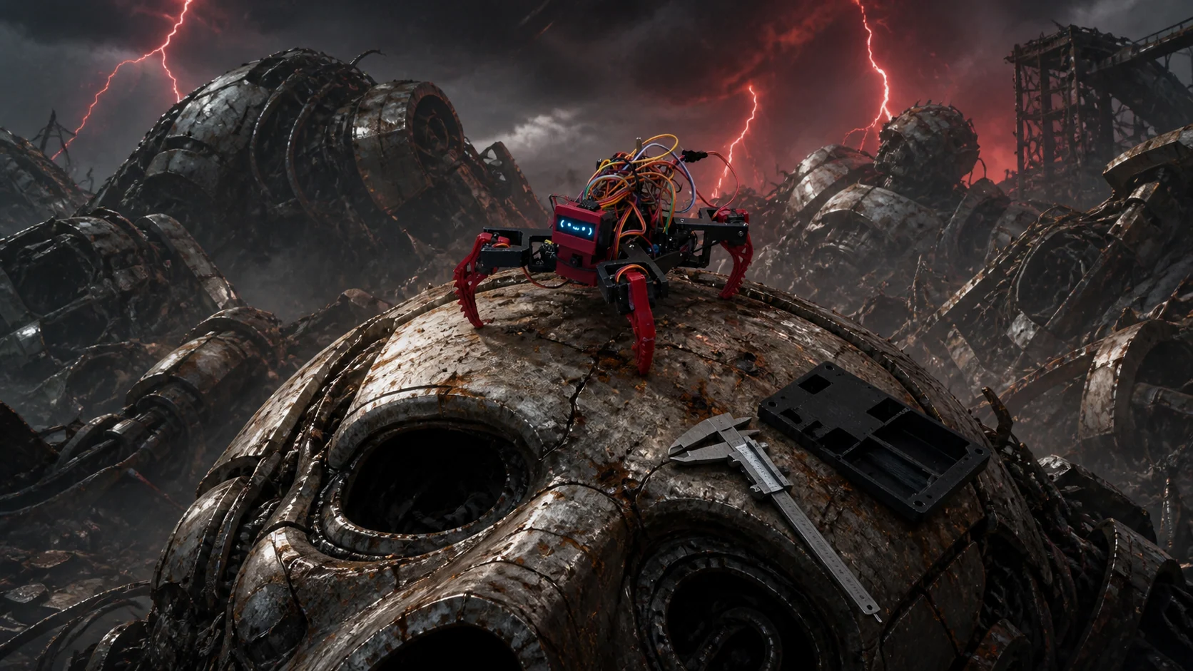
Ainekio’s current photographed body is derived from the open-source Sesame robot: a compact quadruped with four legs, two servo-driven joints per leg, and an OLED face. The assembled August 27 prototype has a low, open black printed chassis, black upper leg frames, red ridged feet, a red front face module, a cyan OLED, and a camera directly below the display. Its controller boards and dense multicolored wiring remain exposed on top.
That construction is not a styling mockup; it is the current physical reference for this site. Sesame supplied a practical printable geometry and an expressive scale, but it does not define Ainekio’s controller, protocol, safety model, media paths, or MetaHuman behavior.
The mechanical design is now evolving around a much denser body-side system. Ainekio needs room and mounting for an ESP32-S3 N16R8 controller, OV3660 camera, OLED display, microphone and speaker interfaces, storage, power distribution, eight servo channels, wiring, ventilation, and service access.
The leg architecture
The robot has eight servo channels: two for each of four legs. The printed upper links attach the legs to the body; the lower links become the feet and determine the usable stance. This is deliberately simple compared with high-degree-of- freedom research quadrupeds.
That simplicity has consequences:
- turns are produced by calibrated gait sequences rather than measured inertial headings;
- a named
turn_left_90asset is an open-loop estimate until the physical body proves it on a real surface; - stability depends on printed geometry, servo centering, transition timing, surface friction, wiring drag, and the power rail;
- expressive poses and walking share the same actuators, range limits, stop path, and fail-safe policy.
The design goal is not to hide those constraints. It is to make a modest body predictable enough that higher-level behavior can rely on it.
The enclosure revisions
The hardware tree contains a long sequence of body and leg revisions rather than one polished final shell. That history is useful: each revision records a fit or packaging decision instead of pretending the first model was final.
The current assembled robot and the current enclosure design are not yet the
same body. The photographed robot still uses its low open frame and visibly
exposed wiring. Separately, the active Frame8 work explores a taller
rectangular enclosure with framed edges and a small upper platform. The added
depth is intended to give the electronics and cable routing a more realistic
home.
As of this status snapshot, the Frame8 Blender and STL files are local active
work, not part of the tracked repository baseline and not installed on the
photographed robot. It should be read as the next packaging experiment—not as a
completed shell.
The site’s generated scenes preserve the photographed open-frame construction. Their ruined cities, alien skies, and gigantic machinery are intentionally fantastical editorial settings; they are not evidence of a physical test.
Controller and primary interfaces
The delivered controller is an ESP32-S3 N16R8 board with 16 MB flash and 8 MB octal PSRAM. The firmware profile is built around that specific memory and pin environment.
The current body design accounts for:
| Interface | Current role |
|---|---|
| Eight servo channels | Four two-joint legs driven through independent MCPWM outputs |
| 128×64 OLED | Face, setup information, and compact state feedback |
| OV3660 camera | Fresh still capture and bounded operator preview |
| Digital microphone | 16 kHz mono capture for wake/VAD/utterance transport |
| I2S speaker path | PCM playback through the external amplifier and speaker |
| microSD | Low-priority bounded logging and capture retention |
| GPIO battery input | Telemetry and warnings under the current owner policy |
| USB and setup AP | Firmware bring-up and first configuration |
The N16R8 board forced a concrete pin-map correction. GPIO33–37 are occupied by octal PSRAM, so an earlier provisional servo mapping could not survive physical bring-up. The current board profile moves affected servo and OLED signals to the pins proven usable on the delivered board.
Power is a hardware boundary
USB bring-up and a moving battery-powered robot are different test conditions. USB is suitable for controller, camera, display, network, storage, and selected audio work. It is not proof that a full servo load will remain stable on the intended battery and regulator path.
The firmware still classifies battery readings for telemetry and warnings, but the current owner policy makes those readings non-authoritative. They do not lock motion or force shutdown. Undervoltage protection belongs to the battery pack’s hardware protection circuit.
That policy avoids a dangerous fiction: a floating or absent ADC divider during USB testing must not be interpreted as a real empty battery and put the robot to sleep. It also means the installed pack and protection behavior need their own physical evidence.
Printed parts are not assembly proof
CAD, a successful slice, and a clean print validate different things. The final body still needs evidence for:
- servo horn alignment and repeatable neutral geometry;
- screw retention without cracked printed bosses;
- cable clearance through the complete gait envelope;
- camera and OLED visibility at standing height;
- microphone placement away from speaker and servo noise;
- airflow and heat under simultaneous network, camera, audio, and motion load;
- battery, regulator, and ground behavior during real gait current spikes;
- enclosure access for flashing, service, and recovery.
The body is therefore best described as an actively engineered prototype. Its shape is concrete, its controller has strong bring-up evidence, and its final assembled acceptance remains open.